Ding Dong Ditch using SDR and Arduino
In this post we will be building a device to play Ding Dong Ditch digitally. The device will ring the doorbell every several seconds without pressing the button. This project is all about reverse engineering radio frequencies using a RLT-SDR and creating hardware using an Arduino.
This project is heavily based upon the Digital Ding Dong Ditch by Samy Kamkar.
The video is a short demonstration of the Ding Dong Ditch device. Once it’s powered by USB (or a battery) it will send out a RF signal every few seconds which will ring the doorbell.
Requirements
For this project you will need several tools and modules to record and send the signal.
Hardware
RTL-SDR: The RTL-SDR is an inexpensive software defined radio using a Realtek chip. The dongle can be used to receive a wide range of frequencies, including those of some wireless doorbells.
Arduino: In this post I will be using an Arduino Nano clone. Arduino is a great platform for cheap and rapid creation of hardware.
433MHz ASK RF Transmitter: For sending the RF signal I will be using a FS1000A (433MHz) RF transmitter. You might want to locate your frequency first, before buying a transmitter for a specific frequency.
Software
RTL-SDR & GQRX: RTL-SDR and Gqrx will be used to locate, record and visualise the radio signal. Instruction about installing RTL-SDR and Gqrx on Linux can be found in Software Defined Radio on Linux post.
Audacity: Audacity is used for taking a closer look at the radio signal in order to demodulate it by hand.
Ding Dong Ditch: The Arduino sketch for this project can be found at my GitHub: github.com/roaldnefs/ding-dong-ditch.
Locate the Signal
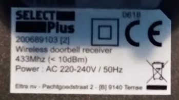
We will start by locating the signal send when pressing the doorbell button. On most devices you will find the frequency on the device itself. In my case the doorbell receiver clearly states that it uses the 433MHz frequency:
Using Gqrx with the RTL-SDR connected to your computer, you will be able to spot signal while pressing the doorbell button.
If you aren’t able to locate the frequency of your doorbell (or you simple cannot find the doorbell receiver), you can always keep pressing the doorbell while you scroll through the spectrum in Gqrx. You might want to check the 315MHz, 433MHz and 900MHz bands first, because they are among the most frequently used bands.
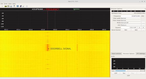
I was able to locate my doorbell signal on 433.879MHz.
Recording and Demodulating the Signal
Modulation allow data to be transmitted via radio via radio frequencies. After locating the signal you’ll need to determine the type of modulation used by the doorbell. By looking at the waterfall in Gqrx I was able to determine that the signal send by the doorbell is amplitude modulated. The most common modulation schemes you will see in radio are:
- Amplitude Modulation (AM)
- Frequency Modulation (FM)
- Phase Modulation (PM)
Amplitude modulation, as the name might suggest, modulates the amplitude while frequency modulation will modulate the frequency. If you are listing to 100.0 FM radio, the signal is actually send between 99.995MHz and 100.005MHz.
By the looks of it, the signal seems to be using amplitude modulation. Using rtl_fm and sox you can record the AM data into a wav file:
rtl_fm -M am -f 433879000 -s 2000000 - | sox -t raw -r 2000000 -e signed-integer -b 16 -c 1 -V1 - doorbell.wav
Since we are dealing with digital information (1s and 0s) the modulation will be more discrete than just AM, common schemes are:
- Amplitude Shift Keying (ASK)
- Frequency Shift Keying (FSK)
- Phase Shift Keying (PSK)
When looking at the audio in Audacity it appears to be sending the same signal multiple times in a row.

If we zoom in to take a closer look at the signal, we can easily see the highs (1s) and lows (0s).
The high and low signals aren’t appearing to be the same length, but the two same patterns keep reappearing:
﹍|﹉﹉|, the high signal seems to be twice as long as the low signal﹍﹍|﹉|, the low signal seems to be twice as long as the high signal
This is something called Pulse Width Modulation (PWM). If we interpret the first signal as a 1 and the second signal as a 0, then we will end up with something like this:
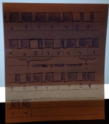
You might want to check multiple samples because the signal isn’t very clear on some spots. Examples of a 1 and 0 signal are shown below:

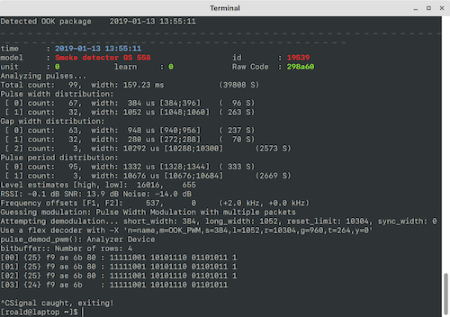
You will be able to get the same result much faster using rtl_433. It might be a good idea to verify you manually demodulated signal using rtl_433 before creating the Arduino. In my case it guesses the modulation type to be Pulse Width Modulation, after demodulation using rtl_433 I end up with the same 1s and 0s as I’ve found manually.
Creating the Arduino
For sending signal we demodulated earlier, I’m using a 433MHz ASK transmitter hooked up to my Arduino nano clone according to the following Fritzing sketch:
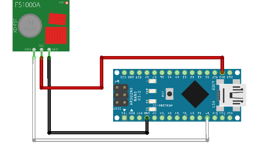
The script for the Arduino can be found on the following GitHub repository: github.com/roaldnefs/ding-dong-ditch. It uses the RCSwitch library for sending the signal. This library is written for power outlet sockets but my doorbell uses the same protocol.
Once the Arduino is powered over USB or by battery, the doorbell should start ringing!